TUFLOW CATCH Tutorial M02 Draft
Page Under Construction
Introduction
In this module, a TUFLOW CATCH pollutant export model with interventions is developed.
TUFLOW CATCH Tutorial Module 02 is built from the pollutant export model created in TUFLOW CATCH Module 01. The completed TUFLOW CATCH Module 01 is provided in the TUFLOW_CATCH_Module_02\Modelling folder of the download dataset as the starting point for this tutorial. If unfamiliar with TUFLOW CATCH, it is recommended to complete TUFLOW CATCH Module 01 prior to starting this tutorial.
GIS Inputs
Create, import and view input data:
Treatment Tables
Treatment tables can be used in TUFLOW CATCH models with interventions. Treatment tables are one of the mass removal methods offered by TUFLOW CATCH. A treatment table is a two dimensional array that defines the proportion of pollutant mass removed from the incoming water based on:
- Incoming pollutant concentration: The concentration of a given pollutant entering the treatment device.
- Note: The concentration units depend on the pollutant. Refer to Section 4.5.3.3.3 of the TUFLOW CATCH Manual for details on unit conventions.
- Flow rate: The volume of water passing through the treatment device (m³/s).
Treatment tables allow users to vary pollutant removal efficiency, recognising that some intervention devices perform better when pollutants enter at higher concentrations and lower flow rates, rather than at lower concentrations with higher flow rates. For more information about treatment tables and their properties, please refer to Section 3.3.1.2 of the TUFLOW CATCH Manual.
For this tutorial, treatment tables for E. coli and clay have been provided:
- In Windows File Explorer, navigate to the TUFLOW_CATCH_Module_02\Tutorial_Data folder. Copy the TC02_ecoli_treatment_001.csv and TC02_clay_treatment_001.csv and paste them in the TUFLOW_CATCH_Module_02\Modelling\TUFLOW\bc_dbase folder.
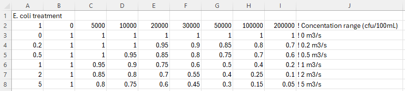
- Open the TC02_ecoli_treatment_001.csv. The first row defines the incoming concentration (cfu/100mL) and the first column defines the incoming flow rate (m³/s). The other values are the mass removal factors, which define the proportion of pollutant removed for a given concentration and flow rate. For example, for an incoming concentration of 100000 cfu/100mL and an incoming flow rate of 5 m³/s, the removal factor is 0.15. The concentration and flow ranges were determined from the outputs of the previous tutorial model (TUFLOW CATCH Tutorial 01).
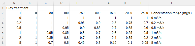
- Open the TC02_clay_treatment_001.csv. This file follows the same structure as the E. coli treatment table, however the incoming concentrations are in mg/L instead of cfu/100mL.


Simulation Control Files
The following steps will require use of a text editor. The tutorial demonstration uses Notepad++. For its configuration information refer to Notepad++ Tips.
TUFLOW CATCH Control File (TCC)
Global Settings
For this tutorial, leave all commands as is. This section of the .tcc was populated in TUFLOW CATCH Tutorial 01.
Catchment Hydraulic Model
For this tutorial, leave all commands as is. This section of the .tcc was populated in TUFLOW CATCH Tutorial 01.
Pollutant Export Model
This block contains commands that control the pollutant export (and other constituent) simulation. For this tutorial, the pollutant export model block must be updated to include interventions.
- Save a copy of TC01_001.tcc as TC02_001.tcc in the TUFLOW_CATCH_Module_02\Modelling\TUFLOWCATCH\runs folder. Open TC02_001.tcc in a text editor.
- In the 'Interventions' section, update the following command to reference the interventions (2d_im) layer created earlier in this tutorial.
Read GIS Intervention == ..\..\TUFLOW\model\gis\2d_im_TC02_001_L.shp ! GIS layer defining interventions
- In the 'Mass Removal Properties' section, add the following device block. This block defines the default mass removal properties for all pollutants across all devices. Including it is considered best practice, as it ensures that all devices have their mass export properties specified. For more information on the mass removal parameters, please refer to Section 4.5.3.5 of the TUFLOW CATCH Manual.
Device == ALL ! Default parameters for all devices
- SED_CLAY, Method == Eqn, Eqn == Constant, Coefficients == 1.0
- WQ_PATH_ECOLI_ALIVE_CFU_100ML, Method == Eqn, Eqn == Constant, Coefficients == 1.0
- WQ_PATH_ECOLI_DEAD_CFU_100ML, Method == Eqn, Eqn == Constant, Coefficients == 1.0
- SED_CLAY, Method == Eqn, Eqn == Constant, Coefficients == 1.0
- Set the mass removal properties for intervention devices 'trench1' and 'trench2'. These devices are placed around the edges of paddocks C and D to manage the E. coli runoff.
Device == trench1, trench2 ! Defines mass removal properties for trench1 and trench2
- SED_CLAY, Method == Eqn, Eqn == Constant, Coefficients == 0.4
- WQ_PATH_ECOLI_ALIVE_CFU_100ML, Method == Eqn, Eqn == Constant, Coefficients == 0.9
- WQ_PATH_ECOLI_DEAD_CFU_100ML, Method == Eqn, Eqn == Constant, Coefficients == 0.9
- SED_CLAY, Method == Eqn, Eqn == Constant, Coefficients == 0.4
- Set the mass removal properties for intervention device 'retentionBasin'. This device is place parallel to the road on the eastern side of the model. It has been placed between paddockB and the culvert under the road to minimise clay and E. coli runoff.
Device == retentionBasin ! Defines mass removal properties for retentionBasin
- SED_CLAY, Method == Eqn, Eqn == Constant, Coefficients == 0.8
- WQ_PATH_ECOLI_ALIVE_CFU_100ML, Method == Table, Path == ..\..\TUFLOW\bc_dbase\TC02_ecoli_treatment_001.csv
- WQ_PATH_ECOLI_DEAD_CFU_100ML, Method == Table, Path == ..\..\TUFLOW\bc_dbase\TC02_ecoli_treatment_001.csv
- SED_CLAY, Method == Eqn, Eqn == Constant, Coefficients == 0.8
- Set the mass removal properties for intervention devices 'bufferStrip1' and 'bufferStrip2'. These devices are placed strategically to manage clay sediment runoff.
Device == bufferStrip1, bufferStrip2 ! Defines mass removal properties for bufferStrip1 and bufferStrip2
- SED_CLAY, Method == Table, Path == ..\..\TUFLOW\bc_dbase\TC02_clay_treatment_001.csv
- WQ_PATH_ECOLI_ALIVE_CFU_100ML, Method == Eqn, Eqn == Constant, Coefficients == 0.4
- WQ_PATH_ECOLI_DEAD_CFU_100ML, Method == Eqn, Eqn == Constant, Coefficients == 0.7
- SED_CLAY, Method == Table, Path == ..\..\TUFLOW\bc_dbase\TC02_clay_treatment_001.csv
- Save the .tcc.
Receiving Model
For this tutorial, leave all commands as is. This section of the .tcc will be discussed in TUFLOW CATCH Tutorial 03.
Running the Simulation
- In Windows File Explorer, navigate to the TUFLOWCATCH\runs folder. Save a copy of _run_TC01_CATCH.bat as _run_TC02_CATCH.bat maybe change name?? and open the file in a text editor.
- Update the batch file to reference the TC02_001.tcc:
set exe="..\..\..\..\exe\TUFLOWCATCH\2025.1.0\TUFLOWCATCH.exe"
%exe% TC02_001.tcc - Double click the batch file in file explorer to run the simulation.
Troubleshooting
See tips on common mistakes and troubleshooting steps if the model doesn't run:
Check Files and Results Output
Complete the steps outlined in the following links to review check files and simulation results from the TUFLOW CATCH pollutant export model simulation:
Conclusion
- Intervention devices were added to a TUFLOW CATCH Pollutant Export model.
- Check files were used to review the placement of intervention devices.
- TUFLOW CATCH interventions summary and TUFLOW map outputs were assessed to observe the mass removal for each intervention device.
| Up |
|---|