Tutorial M11
Introduction
In this module, the creek is represented as a 1D open channel embedded into the 2D floodplain.
Since the release of sub-grid sampling (SGS), 1D open channels may no longer be required if the DEM is at a fine resolution. If the DEM resolution is too coarse (for example in the below image), 1D open channel or quadtree may be required. The recommended approach is to use a quadtree model as demonstrated in Module 7, however, if the DEM is too coarse and cross section data is available, 1D open channel can be used.

The GIS layers are:
- TGC layers:
- 2d_code: A layer containing polygons that define the cell codes (active and inactive).
- 2d_zsh: A layer used to reinforce top of bank elevations.
- ECF layers:
- 1d_nwk: A layer used to define culverts and open channels in 1D.
- 1d_xs: A layer used to reference cross section data.
- 1d_bc: A layer used to define 1D boundary conditions.
- 1d_wll: A layer used to define 1D water level lines (to display 1D results in 2D map outputs).
- TBC layers:
- 2d_bc: A layer defining the locations of 1D/2D boundaries.
- TCF layers:
- 0d_rl: A layer defining the reporting locations.
Module 11 builds from the model created in Module 2. The completed Module 2 model is provided in the Module_11\TUFLOW folder.
Part 1 - 1D Open Channel with Culverts
Simulate 1D open channel model with culverts conveying flow beneath roads.
GIS Inputs
Create, import and view input data:
Boundary Condition Database (bc_dbase)
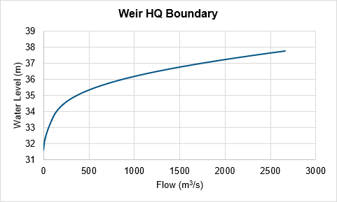
Update the bc_dbase with a reference to the new weir outflow:
- Navigate to the Module_11\Tutorial_Data folder. Copy the Weir_HQ.csv into the Module_11\TUFLOW\bc_dbase folder.
- Open the file, it contains a water level (head) versus flow boundary condition for the water leaving the model:
- Save a copy of the bc_dbase.csv as bc_dbase_M11_001.csv.
- Open the file and add the additional weir boundary condition:
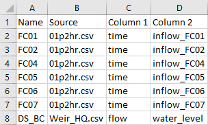
- Save the bc_dbase.


Simulation Control Files
ESTRY Control File (ECF)
A new control file, the ESTRY Control File (ECF), is introduced. ESTRY is TUFLOW’s 1D hydraulic solver and includes all of the 1D files and commands.
- Create a new text file M11_001.ecf and save it in the Module_11\TUFLOW\model folder.
- Add the following command lines:
QGIS - SHP
! 1D TIME CONTROL
Timestep == 0.5 ! Specifies a 1D computational timestep as 0.5 seconds
! 1D ELEMENTS
Read GIS Network == gis\1d_nwk_M03_culverts_001_L.shp ! Defines culverts
Read GIS Network == gis\1d_nwk_M11_channels_001_L.shp ! Reads in open channels
Read GIS Table Links == xs\1d_xs_M11_channels_001_L.shp ! References cross-section data stored in separate csv files
! 1D BOUNDARY CONDITIONS
Read GIS BC == gis\1d_bc_M11_001_P.shp ! Reads in 1D boundary conditions
! 1D WATER LEVEL LINES
Read GIS WLL == gis\1d_wll_M11_001_L.shp ! Displays 1D results in 2D map output result files
QGIS - GPKG
! 1D TIME CONTROL
Timestep == 0.5 ! Specifies a 1D computational timestep as 0.5 seconds
! 1D ELEMENTS
Read GIS Network == 1d_nwk_M03_culverts_001_L ! Defines culverts
Read GIS Network == 1d_nwk_M11_channels_001_L ! Reads in open channels
Read GIS Table Links == 1d_xs_M11_channels_001_L ! References cross-section data stored in separate csv files
! 1D BOUNDARY CONDITIONS
Read GIS BC == 1d_bc_M11_001_P ! Reads in 1D boundary conditions
! 1D WATER LEVEL LINES
Read GIS WLL == 1d_wll_M11_001_L ! Displays 1D results in 2D map output result files
- Save the ECF.
TUFLOW Geometry Control File (TGC)
- Save a copy of the M02_001.tgc as M11_001.tgc in the Module_11\TUFLOW\model folder.
- Open the M11_001.tgc in a text editor and add the following line after the 'Read GIS Code' command:
QGIS - SHP
Read GIS Code == gis\2d_code_M11_null_creek_001_R.shp ! Deactivates cells where the channel has been modelled in 1D
QGIS - GPKG
Read GIS Code == 2d_code_M11_null_creek_001_R ! Deactivates cells where the channel has been modelled in 1D
- Add the following line after the 'Read GIS Z Shape' command:
QGIS - SHP
Read GIS Z Shape == gis\2d_zsh_M11_hx_001_L.shp | gis\2d_zsh_M11_hx_001_P.shp ! Defines the bank crest levels
QGIS - GPKG
Read GIS Z Shape == 2d_zsh_M11_hx_001_L | 2d_zsh_M11_hx_001_P ! Defines the bank crest levels
- Save the TGC.
The line and point 2d_zsh files are read by the same command separated by a vertical line, by reading both of these layers on the same command line enables them to be linked.
TUFLOW Boundary Control File (TBC)
- Save a copy of the M01_001.tbc as M11_001.tbc in the Module_11\TUFLOW\model folder.
- Open the M11_001.tbc in a text editor and comment out or delete the below line, 1D boundaries are used instead:
QGIS - SHP
! Read GIS BC == gis\2d_bc_M01_001_L.shp ! Reads in 2D boundaries
QGIS - GPKG
! Read GIS BC == 2d_bc_M01_001_L ! Reads in 2D boundaries
- Add reference to the new boundaries at the end of the TBC:
QGIS - SHP
! INTERNAL 1D/2D BOUNDARIES
Read GIS BC == gis\2d_bc_M03_culverts_001_P.shp ! Links 1D culverts to 2D domain
Read GIS BC == gis\2d_bc_M11_hx_001_L.shp ! Reads in HX boundaries linking 1D channel to 2D domain
QGIS - GPKG
! INTERNAL 1D/2D BOUNDARIES
Read GIS BC == 2d_bc_M03_culverts_001_P ! Links 1D culverts to 2D domain
Read GIS BC == 2d_bc_M11_hx_001_L ! Reads in HX boundaries linking 1D channel to 2D domain
- Save the TBC.
TUFLOW Control File (TCF)
- Save a copy of the M02_5m_001.tcf as M11_5m_001.tcf in the Module_11\TUFLOW\runs folder.
- Open the M11_5m_001.tcf in a text editor and add the following line in the 'Model Inputs' section:
ESTRY Control File == ..\model\M11_001.ecf ! Reference the ESTRY (1D) Control File
- Make the following reference updates:
QGIS - SHP
Geometry Control File == ..\model\M11_001.tgc ! Reference the TUFLOW Geometry Control File
BC Control File == ..\model\M11_001.tbc ! Reference the TUFLOW Boundary Conditions Control File
BC Database == ..\bc_dbase\bc_dbase_M11_001.csv ! Reference the Boundary Conditions Database
QGIS - GPKG
Spatial Database == ..\model\gis\M11_001.gpkg ! Specify the location of the GeoPackage Spatial Database
Geometry Control File == ..\model\M11_001.tgc ! Reference the TUFLOW Geometry Control File
BC Control File == ..\model\M11_001.tbc ! Reference the TUFLOW Boundary Conditions Control File
BC Database == ..\bc_dbase\bc_dbase_M11_001.csv ! Reference the Boundary Conditions Database
- Remove reference to the 2D plot outputs and replace with reference to the reporting locations:
QGIS - SHP
! Read GIS PO == ..\model\gis\2d_po_M01_001_L.shp ! Reads in plot output line
! Read GIS PO == ..\model\gis\2d_po_M01_001_P.shp ! Reads in plot output point
Read GIS Reporting Location == ..\model\gis\0d_rl_M11_001_L.shp ! Reads in reporting location line
Read GIS Reporting Location == ..\model\gis\0d_rl_M11_001_P.shp ! Reads in reporting location point
QGIS - GPKG
! Read GIS PO == 2d_po_M01_001_L ! Reads in plot output line
! Read GIS PO == 2d_po_M01_001_P ! Reads in plot output point
Read GIS Reporting Location == 0d_rl_M11_001_L ! Reads in reporting location line
Read GIS Reporting Location == 0d_rl_M11_001_P ! Reads in reporting location point
- Save the TCF.
Running the Simulation
- Save a copy of _run_M02_HPC.bat as _run_M11_HPC.bat in the Module_11\TUFLOW\runs folder.
- Update the batch file to reference the M11_5m_001.tcf :
set exe="..\..\..\exe\2023-03-AF\TUFLOW_iSP_w64.exe"
set run=start "TUFLOW" /wait %exe% -b
%run% M11_5m_001.tcf
- Double click the batch file in file explorer to run the simulation.
Troubleshooting
See tips on common mistakes and troubleshooting steps if the model doesn't run:
Check Files
While the model is running, review the added features are specified correctly:
Results
When the model is finished, review the results:
Part 2 - 1D Open Channel with 1D Bridges and Weir inflow (2D) and Outflow (1D)
Simulate 1D open channel model with 1D bridges conveying flow beneath roads. 1D weir is used to convey flow overtopping the downstream road.
GIS Inputs
Create, import and view input data:
Simulation Control Files
ESTRY Control File (ECF)
- Save a copy of the M11_001.ecf as M11_002.ecf in the Module_11\TUFLOW\model folder.
- Open the M11_002.ecf in a text editor and update the following reference:
QGIS - SHP
Read GIS Network == gis\1d_nwk_M11_culverts_002_L.shp ! Defines culverts
QGIS - GPKG
Read GIS Network == 1d_nwk_M11_culverts_002_L ! Defines culverts
- Add the following commands:
QGIS - SHP
Read GIS Network == gis\1d_nwk_M11_bridges_002_L.shp ! Defines bridges
Read GIS Network == gis\1d_nwk_M11_weirs_002_L.shp ! Defines weirs
Read GIS Table Links == xs\1d_xs_M11_bridges_002_L.shp ! References bridges cross section data stored in separate csv
Read GIS Table Links == xs\1d_xs_M11_weirs_002_L.shp ! References weirs cross section data stored in separate csv
QGIS - GPKG
Read GIS Network == 1d_nwk_M11_bridges_002_L ! Defines bridges
Read GIS Network == 1d_nwk_M11_weirs_002_L ! Defines weirs
Read GIS Table Links == 1d_xs_M11_bridges_002_L ! References bridges cross section data stored in separate csv
Read GIS Table Links == 1d_xs_M11_weirs_002_L ! References weirs cross section data stored in separate csv
- Save the ECF.
TUFLOW Geometry Control File (TGC)
- Save a copy of the M11_001.tgc as M11_002.tgc in the Module_11\TUFLOW\model folder.
- Open the M11_002.tgc in a text editor and update the following references:
QGIS - SHP
Read GIS Code == gis\2d_code_M11_null_creek_002_R.shp ! Deactivates cells where the channel has been modelled in 1D
Read GIS Z Shape == gis\2d_zsh_M11_hx_002_L.shp | gis\2d_zsh_M11_hx_001_P.shp ! Defines the bank crest levels
QGIS - GPKG
Read GIS Code == 2d_code_M11_null_creek_002_R ! Deactivates cells where the channel has been modelled in 1D
Read GIS Z Shape == 2d_zsh_M11_hx_002_L | 2d_zsh_M11_hx_001_P ! Defines the bank crest levels
- Save the TGC.
TUFLOW Boundary Control File (TBC)
- Save a copy of the M11_001.tbc as M11_002.tbc in the Module_11\TUFLOW\model folder.
- Open the M11_002.tbc in a text editor and update the following reference:
QGIS - SHP
Read GIS BC == gis\2d_bc_M11_hx_002_L.shp ! Reads in HX boundaries linking 1D channel to 2D domain
QGIS - GPKG
Read GIS BC == 2d_bc_M11_hx_002_L ! Reads in HX boundaries linking 1D channel to 2D domain
- Save the TBC.
TUFLOW Control File (TCF)
- Save a copy of the M11_5m_001.tcf as M11_5m_002.tcf in the Module_11\TUFLOW\runs folder.
- Open the M11_5m_002.tcf in a text editor and make the following reference updates:
QGIS - SHP
ESTRY Control File == ..\model\M11_002.ecf ! Reference the ESTRY (1D) Control File
Geometry Control File == ..\model\M11_002.tgc ! Reference the TUFLOW Geometry Control File
BC Control File == ..\model\M11_002.tbc ! Reference the TUFLOW Boundary Conditions Control File
QGIS - GPKG
Spatial Database == ..\model\gis\M11_002.gpkg ! Specify the location of the GeoPackage Spatial Database
ESTRY Control File == ..\model\M11_002.ecf ! Reference the ESTRY (1D) Control File
Geometry Control File == ..\model\M11_002.tgc ! Reference the TUFLOW Geometry Control File
BC Control File == ..\model\M11_002.tbc ! Reference the TUFLOW Boundary Conditions Control File
- Save the TCF.
Running the Simulation
Update the batch file created in the first part of Module 11 to reference the M11_5m_002.tcf file. Save the batch file and double click it in file explorer to run the simulation.
Troubleshooting
See tips on common mistakes and troubleshooting steps if the model doesn't run:
Check Files
While the model is running, review the added features are specified correctly:
Results
When the model is finished, review the results:
Conclusion
- A model with 1D open channel embedded into 2D floodplain was created.
- The 1D open channel conveyed flow underneath the roads through 1D culverts.
- Bridges were modelled in 1D, with overflow occurring in the 2D for the upstream bridge and 1D weir for the downstream bridge.
| Up |
|---|