Tutorial M11 001 GIS Inputs QGIS
Introduction
QGIS is used to create, import and view input data.
TUFLOW Project Re-Configuration
Re-configure the TUFLOW project to use and save empty files to the correct folder:
- Go to Plugins > TUFLOW > Editing > Configure / Create TUFLOW Project.
- Change the folder which contains TUFLOW to the Module_11 folder. This is the only change required, the model folder structure and template empty files are supplied from previous model.
Note: The 'results' and 'check' folder get automatically created when the TUFLOW model is run.
- Click 'OK' and save the workspace by selecting Project > Save As.
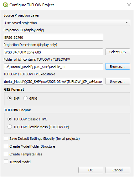
- Set the workspace projection to EPSG:32760, see Set the Projection.

Method
Navigate to the Module_11\Tutorial_Data folder:
- Copy and save the xs folder into the Module_11\TUFLOW\model folder.
- Copy and save all the below layers into the Module_11\TUFLOW\model\gis folder:
- 1d_bc_M11_001_P
- 1d_nwk_M03_culverts_001_L
- 1d_nwk_M11_channels_001_L
- 1d_wll_M11_001_L
- 2d_bc_M03_culverts_001_P
- 2d_bc_M11_hx_001_L
- 2d_code_M11_null_creek_001_R
- 2d_zsh_M11_hx_001_L
- 2d_zsh_M11_hx_001_P
1D Cross Section
A 1D open channel requires cross sections for processing of the channel geometry. For each cross section there is an individual comma separated csv file:
- Load the 1d_xs_M11_channels_001_L.shp from the Module_11\TUFLOW\model\xs folder into QGIS and use the 'Apply TUFLOW Styles to Open Layers'.
- The cross sections extend further than the 2d_code layer and DEM, here the model transitions from a 1D/2D model to a 1D only model. This method can be used where cross section data is available but topography data is not.
- Use the 'Identify Features' tool to inspect a cross section line. Each line has a unique name in the 'Source' attribute field that links to a cross section csv contained within the xs folder. Type attribute 'XZ' specifies distance vs elevation cross section:
- Open the TUFLOW Viewer, the 1d_xs file automatically appears with a time series result 'XZ' showing. Select a 1d_xs line and view the cross section:
1D Channels
A 1d_nwk layer is used to model open channels. It contains information on inverts and to obtain data from the cross section the 1d_nwk and 1d_xs must be snapped:
- Load the 1d_nwk_M11_channels_001_L.shp from the Module_11\TUFLOW\model\gis folder into QGIS and use the 'Apply TUFLOW Styles to Open Layers'.
- There are three 1d_nwk types used:
- S - standard open channel.
- W - weir.
- X - connecting channel used for side channels entering the main channel.
- Use the 'Identify Features' tool to inspect the attributes of the three 1d_nwk types:
1D Boundary Conditions
The 1D model extents both upstream and downstream of the 2D active domain:
- Load the 1d_bc_M11_001_P.shp from the Module_11\TUFLOW\model\gis folder into QGIS and use the 'Apply TUFLOW Styles to Open Layers'.
- Use the 'Identify Features' tool to inspect the attributes of the three boundaries. A QT type (flow vs time) hydrograph is used to apply flow at the upstream boundary and a HQ (water level vs flow) boundary is used to remove flow from the downstream boundary based on a water level vs flow curve:
1D Culverts
1D culverts are included in a separate 1d_nwk layer. 1D culverts are described in detail in Module 3:
- Load the 1d_nwk_M03_culverts_001_L.shp from the Module_11\TUFLOW\model\gis folder into QGIS and use the 'Apply TUFLOW Styles to Open Layers'.
- There are two 1d_nwk types used:
- C - circular culvert.
- R - rectangular culvert.
- Two culverts within the open channel link upstream 1D channel to the downstream 1D channel underneath the roads, the culvert to the east is embedded into the 2D domain directly. Use the 'Identify Features' tool to inspect the attributes:
1D / 2D Links
The culvert on the east is connected to the 2D domain using 2d_bc layer SX type connection. It removes water out of the upstream cell(s) and deposits water back at the downstream cell(s):
- Load the 2d_bc_M03_culverts_001_P.shp from the Module_11\TUFLOW\model\gis folder into QGIS and use the 'Apply TUFLOW Styles to Open Layers'.
- The 2d_bc SX points are snapped to the 1d_nwk culvert:
The 1D open channel is linked to the 2D using a 2d_bc layer HX and CN type connections:
- Load the 2d_bc_M11_hx_001_L.shp from the Module_11\TUFLOW\model\gis folder into QGIS and use the 'Apply TUFLOW Styles to Open Layers'.
- The 2d_bc HX type lines run along the top of bank. In HX type, the H indicates a head (water level) boundary and the X indicates a water level value coming from the 1D model. Once the water level in the 1D exceeds the water level in the 2D boundary cell, water can enter from 1D channel to 2D domain and vice versa. For water to flow in and out of floodplain overbank areas, HX lines extending into the floodplain at the upstream and downstream are required. Without them, the flow is assumed to be contained within bank which may not be the case.
- The CN lines connect the HX lines to the 1D channel. Where a CN line is connected to the HX line, the water level from the 1D nodes is transferred to the HX line. In between 1D nodes a linear interpolation of water level is applied.
2D Breaklines
The water level is transferred between 1D to 2D through HX cells. It is important the 2D cell elevation reflects the correct level that water can spill out from one domain to another, thick breakline is required. 2D breaklines are described in detail in Module 2:
- Load the following layers into QGIS from the Module_11\TUFLOW\model\gis folder and use the 'Apply TUFLOW Styles to Open Layers':
- 2d_zsh_M11_hx_001_L.shp
- 2d_zsh_M11_hx_001_P.shp
- The 2d_zsh line layer is used to define breaklines along the bank of the channel:
- No ‘Z’ attribute is specified, the elevations are taken from the 2d_zsh point layer.
- The breakline has the same Shape_Width as the cell size, this is a thick breakline modifying whole cells.
- The Shape_Option of 'MAX' is specified. The Zpt elevations only changes when the Z shape elevation at the Zpt is higher. The purpose of the Z shape is to enforce the highest elevations along the bank of the channel.
- The 2d_zsh point layer is used to apply elevation to the breaklines:
- The values in the 'Z' attribute are elevations assigned to each point and are interpolated along the breakline.
- The points must be snapped to the vertices of the 2d_zsh line to instruct TUFLOW that these layers are linked. If no points are in the layer, the elevation on the line object is used, i.e. the elevation along the line does not vary.

Deactivate 2D Cells
The area of the 1D open channel defined by the 1D/2D HX boundaries must be removed from the active 2D cells:
- Load the 2d_code_M11_null_creek_001_R.shp from the Module_11\TUFLOW\model\gis folder into QGIS and use the 'Apply TUFLOW Styles to Open Layers'.
- The 2d_code layer is used to deactivate the area representing the 1D open channel with attribute of '0'. All cells within the polygon are removed from the 2D computations.
Water Level Lines
Water Level Line (WLL) are used to display 1D results in map outputs. WLL do not change 1D hydraulic computations and are only used to display 1D results in plan (2D) formats. For more information on WLL, refer to the TUFLOW Manual:
- Load the 1d_wll_M11_001_L.shp from the Module_11\TUFLOW\model\gis folder into QGIS and use the 'Apply TUFLOW Styles to Open Layers'.
- The 1d_wll layer must be digitised perpendicular to the flow direction and from left to right looking downstream. An attribute of '2.5' is specified for all lines as a minimum distance interval along the WLL to generate triangulation points.
Reporting Locations
Reporting locations allow for the plotting of time series results across both the 1D and 2D sections of the model. Points are treated as water level output and lines as flow output.
Create a reporting location layer:
- Click on the ‘Import Empty File’ symbol from the TUFLOW Plugin toolbar.
- Select '0d_rl' from the Empty Type list.
- In the Run ID box write 'M11_001'.
- Tick the 'Line' and 'Point' Geometry Type and hit 'OK'. The 0d_rl (reporting location) files appear in the Layers panel.
Copy the line and point from the 2d_po layer:
- Load the 2d_po_M01_001_L.shp and 2d_po_M01_001_P.shp from the Module_11\TUFLOW\model\gis folder into QGIS.
- Right click on the 0d_rl_M11_001_L and toggle on Editing.
- Copy the line from the 2d_po line layer into the 0d_rl line layer.
- Open the attribute table and enter Name as 'Loc1_L'.
- Turn off editing to save the edits.
- Right click on the 0d_rl_M11_001_P and toggle on Editing.
- Copy the point from the 2d_po point layer into the 0d_rl point layer.
- Open the attribute table and enter Name as 'Loc1_P'.
- Turn off editing to save the edits.
- To ensure the point reporting functionality is correct, it needs to be snapped to the start/end of a 1d_nwk line.
- Right click on the 0d_rl_M11_001_P and toggle on Editing.
- Use the 'Vertex Tool' to move the point.
- Enable snapping and use the 'Edit Advanced Configuration' tool to select 1d_nwk_M11_channels_001_L.
- Use the 'Vertex Tool' to snap the point to the start/end of the 1d_nwk line.
- Turn off editing to save the edits.
Conclusion
- A 1d_xs layer was inspected using the TUFLOW Viewer, cross sections were plotted for the 1D open channel.
- A 1d_nwk layer was inspected, three types of 1D channel are used and connected to the 1D cross sections.
- Boundary conditions were defined in the 1D using a 1d_bc layer.
- A 1d_nwk layer was inspected containing information on 1D culverts.
- The 1D open channel model was linked to the 2D using the 2d_bc 'HX' type.
- Breaklines were introduced to enforce the top of bank elevations using 2d_zsh points and lines.
- A 2d_code layer with zero attribute deactivating cells from the 2D domain was inspected.
- A 1d_wll layer was inspected, lines were digitised perpendicular to flow and left to right looking downstream.
- A 0d_rl layer was created to report flow and water level time series for the 1D and 2D domain.
| Up |
|---|